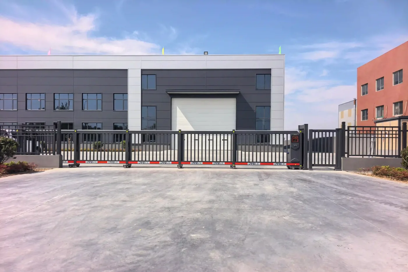
Think about what a cantilever gate foundation is actually asked to do. The leaf is a long piece of aluminum hanging out over the opening, touching nothing. All that overhang has to go somewhere, and it goes straight into two modest blocks of concrete as a twist. Pour them right and the gate glides. Miss by a couple of centimeters? You'll spend years replacing wheels and resetting motor faults.
What follows tracks the foundation section of our installation manual for CAIMEN cantilever gates. Where the manual goes quiet, we've filled in with ordinary concreting practice and said so. It's for the crew with the shovel and the string line, not the sales deck.
Why the footing matters more than the gate
There's no ground rail on a trackless gate. Nothing down there forgives a small mistake. The leaf hangs from a carriage and a set of hanger wheels, and those wheels roll true only when they share one flat plane.
That's the whole game.
Our manual puts the motor cabinet, the gate frame support and the hanger wheels on the same horizontal plane, within ±10 mm. Sounds roomy. It isn't. Picture a 9 m leaf, the length you'd pair with a 6 m clear opening, and imagine how far a slight tilt at the base swings out at the tip.
My take: a scratched finish is an afternoon's touch-up. A crooked footing means a jackhammer. Put your care into the concrete.
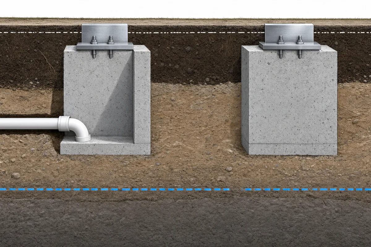
Pit size, concrete grade and layout
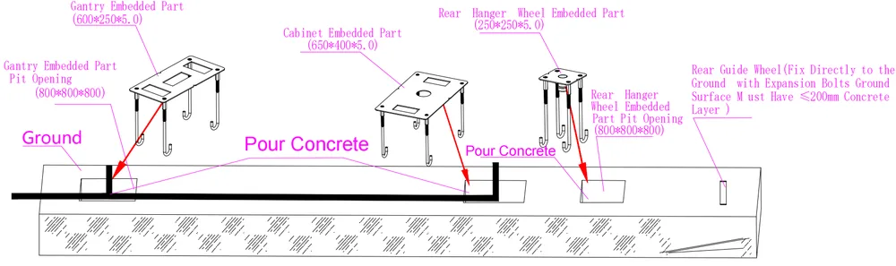
Numbers first. Every pit is 800 x 800 x 800 mm, roughly 31.5 in each way. Fill it with C20 or higher concrete. In the Chinese standard, C20 means about 20 MPa characteristic strength, so when you call the ready-mix plant, ask for an equivalent or stronger structural mix. Don't let them send a sidewalk blend.
Then the layout. Snap one reference line along the gate line before anything else. Our installation manual puts the centers of the pits and the embedded parts 40 cm off that line. Measure from it every time. That fence post or curb you're tempted to use might be out of square, and you won't know until the leaf is hanging.
| Item | Requirement | Field note |
|---|---|---|
| Foundation pit | 800 x 800 x 800 mm | Go deeper in frost country (see below) |
| Concrete | C20 or higher | Order a structural mix, not a flatwork mix |
| Pit and plate centers | 40 cm from the reference line | Mark from one snapped line only |
| Cable trench | 10 x 10 x 10 cm | Runs to the motor cabinet position |
| Conduit | 60 mm diameter PVC | Sweep the bends, don't kink them |
| Cable stub-up | 1.5 m above grade | Tape and bag the ends against rain |
| Level tolerance | ±10 mm, one plane | Cabinet, frame support and hanger wheels |
| Rear hanger wheel | About 1.5 cm lower than the front support wheel | Set on purpose, not by accident |
| Power | Dedicated switch with 6 A breaker, grounded | Bring this to the electrician early |
How long is the opening you're pouring for? On our standard sizing table the gate runs about 1.5 times the clear opening. So 4,000 mm of opening gets a 6,000 mm leaf. At 7,500 mm, you're looking at 11,250 mm. That counterweight tail has to park somewhere, which is why you check the side space before anyone breaks ground. The specifications page has the full dimensions.
Frost depth and soil: where the manual ends
Our manual specifies an 800 mm deep pit. That's not a frost-depth number for your county.
US code handles this separately. Under the International Residential Code, Section R403.1.4, exterior footings go below the local frost depth and at least 12 inches below undisturbed ground, whichever is deeper. Jaspector's code commentary makes the practical point: your local building department has the real answer, and it's often printed right on the permit checklist. Up in Minnesota or northern New York, expect something well past 800 mm.
Simple fix. Hold the 800 x 800 mm footprint and take the depth down to whatever your jurisdiction asks for. If frost lifts one pit and leaves the other alone, you'll blow past 10 mm in a single winter.
Watch the soil, too. Soft fill, organic topsoil, an old backfilled utility trench: none of it holds. Imagine a site where a retired water main runs right under the hanger wheel pit. That pit is going to sink. Dig past the disturbed stuff and pour on firm ground.
Conduit, cable trench and power
Get the electrical path in before the pour. Coring through fresh concrete later is miserable work.
- Cut a 10 x 10 x 10 cm trench from the power source to the cabinet location.
- Lay 60 mm PVC conduit in it, turning up into the cabinet pit.
- Leave 1.5 m of reserved cable standing above finished grade so the electrician has slack.
- Power the gate from its own switch with a 6 A breaker and a solid ground.
Loop detectors on the drawings? LPR cameras, a card reader? Pull a spare conduit now, because an empty pipe in the pour costs next to nothing. You'll find the devices you might wire later on our safety and access control page.
Setting the embedded plates and leveling
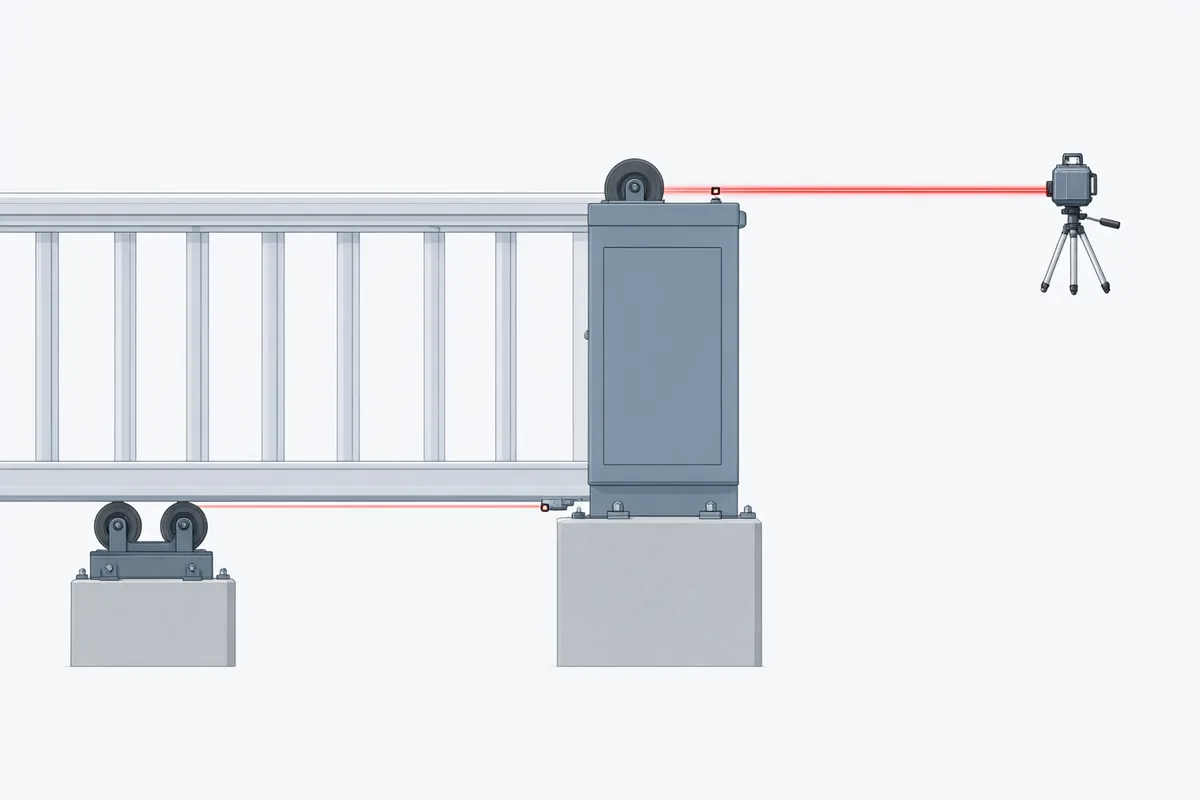
You win or lose the ±10 mm right here. Set the embedded plates on their anchor bolts while the concrete's still workable. Then check three things: height, plane, and distance to the reference line.
The sequence below isn't from the manual. It's field practice we'd suggest:
- Run a laser or water level across every support point and mark a single target elevation.
- Seat the cabinet plate, then the hanger wheel plate, off that same benchmark.
- After vibrating, measure the plate centers again. Still 40 cm from the line? Plates drift.
- Give it 20 minutes and recheck. Concrete slumps, and the plates go with it.
New crews often miss this next part. The rear hanger wheel should finish about 1.5 cm lower than the front cabinet support wheel, and our manual asks for that deliberately. The leaf works like a lever. Dropping the back slightly keeps the far tip from sagging once the full weight settles in. So don't "fix" it to dead level.
Curing before you hang the leaf
Concrete looks hard well before it is. Hang a 10 m aluminum leaf on green concrete and you're loading the anchors at the worst possible moment.
According to the Concrete Network's curing guide, strength rises fastest over the first 3 to 7 days, and full design strength arrives at about 28 days. The guide recommends keeping the surface moist, ideally for 7 days. Cold is the other enemy. Hydration slows sharply below about 50 °F and nearly stops under 40 °F, and the guide sends you to ACI 306 for cold-weather pours.
For your schedule, that means a damp, covered first week. Don't mount the gate or snug the anchor nuts until the mix has gained real strength, and let your engineer or ready-mix supplier name the day. Pouring in Chicago in November? Bring blankets.
Wind loading and reinforcement options
Put solid infill on a cantilever leaf and you've built a sail on a stick. Your foundation has to hold against it.
For standard sites, our installation manual describes optional reinforced embedment for the top and bottom beam profiles, which can resist roughly force 8 to 12 winds on the Beaufort scale. As general guidance, that's enough for plenty of sheltered inland entrances.
Coastal or typhoon-exposed sites are different. They get a custom package, which can include:
- a larger bottom beam section,
- additional embedded plates,
- diagonal tie rods on both sides,
- a larger motor.
Say you're bidding a port perimeter on the Gulf Coast. Raise the wind exposure at the drawing stage. Extra plates change the pit layout, and you want them cast in, not drilled in later. CAIMEN makes four 6005-T6 bottom beam profiles with walls up to 7.0 mm, so stepping up the section doesn't mean redesigning the gate.
Pre-installation checklist
Walk the site with this before the gate truck pulls in:
- Pits 800 mm square, at least 800 mm deep, and below local frost depth.
- C20 or better concrete, cured and covered.
- Plate centers 40 cm from the reference line.
- All supports within ±10 mm of one plane, rear hanger wheel about 1.5 cm low.
- 60 mm conduit in place, cable 1.5 m above grade.
- Dedicated 6 A breaker and ground ready.
- Wind reinforcement plates installed if the site calls for them.
Every box ticked? Then the rest goes fast. Our installation guide takes over from here: hanging the leaf, setting limits, commissioning the safety devices. Got a tricky site? Send the drawings to yifei@gmail.com or reach us through the contact page.
Sources
- Concrete Curing Guide (Concrete Network)
- Footing Depth and Frost Line under IRC 2024 R403.1.4 (Jaspector)
CAIMEN product figures come from our installation manuals and engineering documentation.